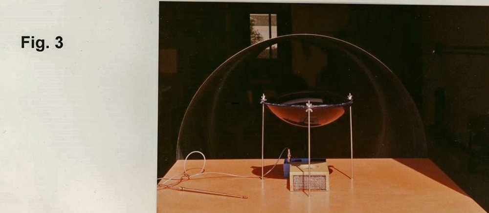
Aerodynamic disks accelerate air flow through roof-mounted heat exchangers to enhance operating efficiency of air conditioning units of tall buildings. Conservative estimates based on wind tunnel tests indicate 26% increase in COP (Coefficient of Performance). Project consulting architect calculated the air conditioning requirements for a 200 ft. high 400,000 ft2 office area building. Using local industrial fabrication and installation estimates, the required 20 ft diameter disk could be sold for $30,000 installed, including overhead and administrative costs. Extremely conservative estimates of $10,000 (probably $15,000-20,000) energy cost savings annually recover the initial expense in 1.5 - 3 years. Disk use by 5% of 3 million U.S. commercial buildings yields both energy cost savings and new industrial-business operations of considerable interest to economy and environment. Project architect found no structural, logistic, legal, or environmental objections to installation of disks on buildings. Fig. 1 shows simplified representation of installed disk.
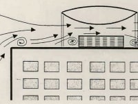
Thermodynamic Considerations - The thermodynamic cycle of most refrigerating systems is shown in Figure 2. Vapor is compressed in process (A - B). Heat is rejected in the condenser on (B - C), with C on the liquid saturation line. The liquid at C is expanded to state D. Heat absorbed from cooled spaces brings the fluid to state A, and the process is repeated. Performance coefficient COP is heat absorbed in D - A referred to compression work in (A - B). In hot ambient conditions the condenser temperature rises, compression work increases and heat absorbed is reduced to (D' - A). If condenser heat rejection increases the process becomes (B - C''), and expands to D". Compression work (A - B) now absorbs heat in (D" - A). With the nominal cycle (A-B-C-D-A), COP = (D - A)/(A - B). With cooling of the condenser COP = (D" - A)/(A - B). Overheated condenser COP = (D' - A)/(A - B). Clearly, small enhancements of heat transfer bring considerable benefits. For Freon 12 and condenser at 110oF COP = 4.6. For condenser at 110oF and 10oF sub-cooling COP = 5.8, an increase of 26%.
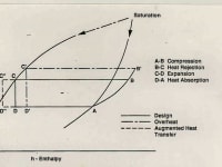
Aerodynamic Testing - Ejector driven 48" diameter blow-down tunnel employing compressed air from adjacent project represented wind over the model (Fig. 3). Condenser model was a 3"x6"x9" box using steel wool as resistance of the cooling coils. The aerodynamic disks of 15" diameter with maximum thickness of 4" and 8" were vacuum molded, with attachment points. Flow visualization employed TiCL4 dispersed by air jets. Average velocities over the condenser and disk models were measured with Kurz anemometers. Spacing between the disk and condenser was varied and the optimum was estimated to be 1" (17%). Measured velocities indicated that at optimum spacing fans in actual condensers could be allowed to rotate freely without any power input.
Design of Disks - Finite element analysis showed that a simple 0.08" 20 ft. diameter shell with 12 radial stiffening rods and mid-radius stiffening ring could withstand all weather conditions, and last 25 years.
Like this entry?
-
About the Entrant
- Name:Andrew Wortman
- Type of entry:individual
- Software used for this entry:Mathcad
- Patent status:none


