


Theoretical analysis
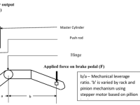
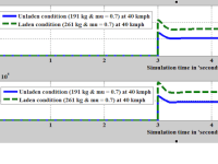
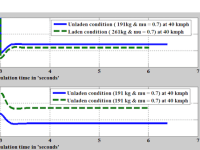
In this work, an endeavor has been presented to modify the conventional rear disc braking system in a motorcycle. In two wheeler, when a pillion load is added, the normal static reaction increases on the rear wheel and during braking operation, the normal dynamic reaction starts decreasing on rear wheel. Furthermore, the normal dynamic reaction on rear wheel is more for laden condition than unladen condition during braking operation that leads to more braking force required between the tire and road surface for laden condition when the magnitude of required braking force is compared with unladen condition. In order to vary the braking force developed at the tire and the road surface, the mechanical leverage (Fig 1) which operates the master cylinder is varied based on the pillion load. This optimized braking force on the disc brake helps to attain the minimum vehicle stopping distance and also helps in preventing sliding. Thus the system results in reducing the stopping distance of the two wheeler and providing a better braking efficiency than a conventional disc braking system. In this project, the mechanical leverage ratio, stopping distance, vehicle deceleration, dynamic normal reaction on rear wheel, braking torque are theoretically calculated and plotted (Fig 2 and Fig 3) when the rear brake is only applied at 3rd sec of the simulation time for different load conditions (Unladen mass = 191kg, laden mass = 261 kg including 70 kg pillion rider mass) on a two wheeler for the coefficient of adhesion (0.7) between the tire and road surface at an motorcycle speed of 40 kmph using MATLAB software.
In Fig-2, rear brake is applied at 3rd sec (Assumed) mechanical leverage starts to vary from the 3rd sec .Mechanical leverage ratio varies from 0 to 4 and finally it settled down at 3.7 for laden condition. Similarly it varies from 0 to 2.7 and finally settled down to 2 for unladen condition. This variation in mechanical leverage ratio is due to the load transfer effect.
Experimental set up
A load cell which is fitted under the pillion seat is used to measure the pillion load and it sends signal to the microcontroller which actuate stepper motor to vary the position of master cylinder (Ref. Fig 1 - ‘b’ length from the hinged point is varied by rack and pinion arrangements) to vary the mechanical leverage ratio in the braking system. A look up table is fed in the microcontroller to actuate the stepper motor based on load cell input. In Fig 1, ‘b’ arm is made of two concentric cylindrical parts. The outer cylinder is fixed to hinged point of the pedal. A rack is attached with the inner cylinder which is movable. When the pinion rotates, the rack gets linear movement. Thus the ‘b’ length is being varied that varies the mechanical leverage ratio (b/a- ‘b’ length is varied by keeping ‘a’ length as constant) which operates the master cylinder.
Like this entry?
-
About the Entrant
- Name:Ganesh Vinayaga Sundaram
- Type of entry:teamTeam members:Ganesh V, Assistant Professor
Sivagnana Subramanian, Assistant Professor
Abinaya T, Student - Software used for this entry:MATLAB
- Patent status:none