

Abstract— In PWM (Pulse Width Modulation), by modulating the relative time intervals corresponding to conduction and non-conduction periods, it is possible to spread the voltage during the period in such a way as to make the conduction time of the switching device practically proportional to the instantaneous value of the fundamental. The output voltage of PWM power inverters exhibits harmonic distortion due to the modulation algorithm, modulation frequency (2-20 KHz), modulation of the switching transients (100 KHz-100MHz), dc bus voltage, dead times(DT), voltage drop across switches(vds). As a result, loads driven by these inverters exhibit greater order of fluctuations. This work proposes to reduce the harmonic distortion using harmonics attenuators, modulation variations and reduce the distortion caused by dead times and voltage drop across switches using an efficient pulse compensation that has a feedback path which computes width of each PWM pulse and reports whether or not the pulse has to be compensated, thereby using the ideal area optimally.
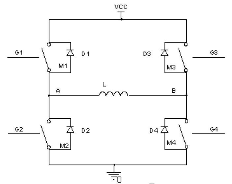
Inverters using Pulse Width Modulation (PWM) switching use semiconductor devices to transform the DC power into controlled AC power. PWM switching is an efficient way to generate AC power, allowing flexible control of the output magnitude and frequency. However, all PWM methods inherently generate harmonics and noise originating in the high dv/dt and di/dt semiconductor switching transients. In order to reduce harmonics and switching noise, external filtering needs to be added. The output voltage control of inverters require varying both the number of pulses per half-cycle as well as the pulse widths that are generated by modulating techniques.But certain harmonics are undesirable in reducing certain effects such as harmonic torque, heating in motors, noise, interferences and oscillations. The PWM waveform is generated by comparing a reference signal and a carrier waveform.The PWM waveform controls the Insulated Gate Bipolar Transistor (IGBT) switches to generate the AC output. When the reference signal is bigger than the carrier waveform, the upper IGBT is triggered on (lower IGBT being off) and positive DC voltage is applied to the inverter output phase (A). In the other case, when the reference signal is smaller than the triangular carrier waveform, the lower IGBT is turned on (upper IGBT being off) and negative DC voltage is applied to the inverter output. The reference signal magnitude and frequency determine the amplitude and the frequency of the output voltage. The frequency of the carrier waveform is called the modulation frequency. In order to generate more precise sinusoidal AC voltage waveforms and keeping the size of the LC filter small, high modulation frequencies are generally used.
Methods of reducing THD caused by DT and VDS and its compensation have been presented.
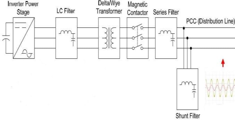
Using the LC, Series and Shunt filter the THD could be reduced to as low as 3-4 %.
On the other hand the DT compensation algorithm is a very efficient way to reduce the THD in inverters. According to the achieved experimental data, using the DT compensation the THD could be reduced from 18-20% to 0.2-0.6%.
Like this entry?
-
About the Entrant
- Name:Roni Mukherjee
- Type of entry:teamTeam members:Mr. Roni Mukherjee
Mr. Debaditya Chakraborty
Mr. Md. Sohail Mallick - Software used for this entry:MATLAB
- Patent status:none