


Hydroelectric power plant is one of the renewable electricity resources extensively used for power production. But these power plants are located near hilly regions and are not designed for plain areas. Most of the perennial rivers have good water current throughout the years. This high water current can be used to produce electricity by using special mechanical arrangements.
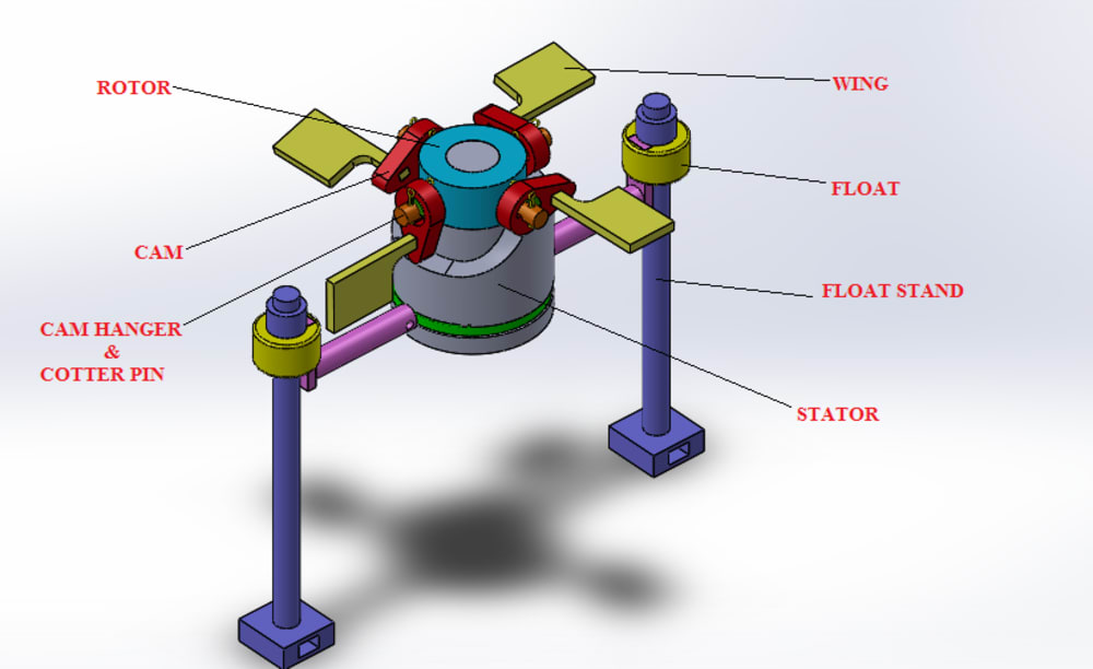
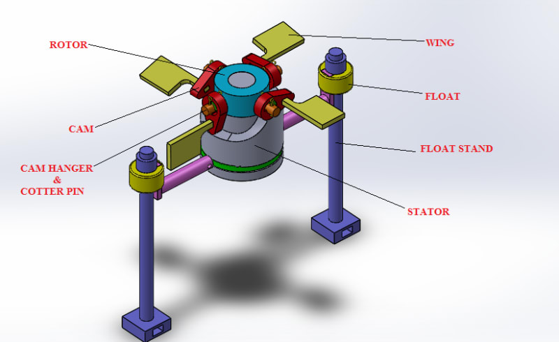
Wing arrangements in the design are the important to produce the required rotary motion for the water flow in the river. The wing is designed to trap the energy supplied from the flowing water. The fabrication of this dynamic wing turbine is simple and can be implemented in all the rivers across the nation. Since the power produced by this method will be environmental friendly one and can be a better alternative for future power requirements.
The water flowing in the river makes the blade to rotate in an unique direction which is used for power generation. The design can be used as submersible one, which makes it more interesting for other application.
WORKING PRINCIPLE:
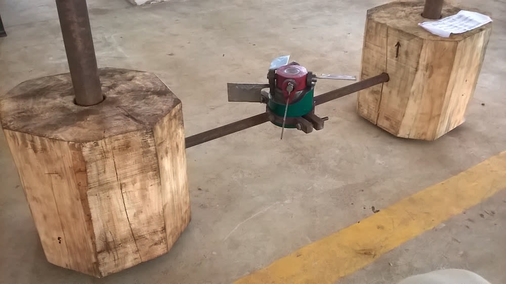
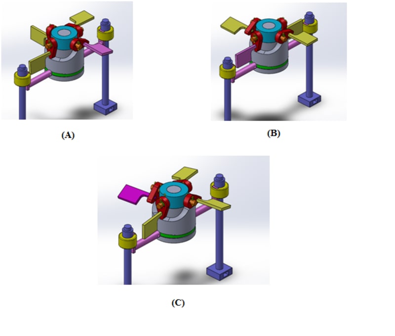
1. The proposed model of the turbine is fixed in the river bed as shown in illustration 1.
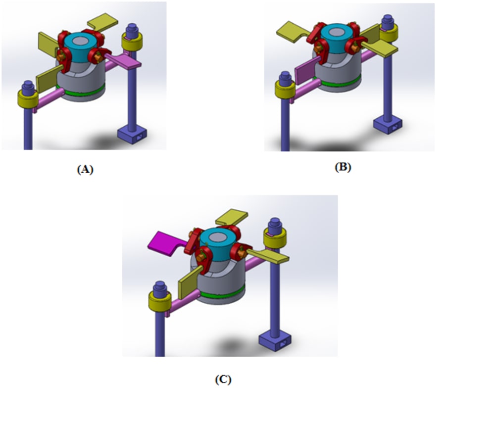
2. For illustration purpose the color of one wing is changed into pink color.
3. In the illustration 2(A), the wing which is perpendicular to the rotor axis receives the impact energy from the flowing river water.
4. This impact energy is converted into a couple and a turning moment is created and hence the wing which is pink in color comes perpendicular to the flow and the other three wings become parallel to the flow as shown in illustration 2(B).
5. Now the wing in pink color receives the impact energy from the flowing water and again a turning moment is created as a result the wing becomes parallel to the flow and the next wing comes perpendicular to the flow as shown in illustration 2(C).
6. This process will continue and a uni-directional rotational motion will be obtained.
FABRICATION:
Fabrication of stator:
Stator is the base of the turbine which is solid and cylindrical in shape having some grooves in it in order to produce a uni directional flow. The groove in the stator is made in CNC MILL.
Fabrication of Rotor:
Rotor is the movable part of the turbine which is hollow cylindrical in shape having four holes in its face to hold the cam and wing arrangements. These holes and the center hollow is made in lathe machine.
Fabrication of cam and wing:
The cam used here is the combination of radial and cylindrical cam. The main purpose of the cam is to make the wings of the turbine parallel and perpendicular to the flow of water.
The cam is fabricated with the hekp of WIRECUT ELECTRICAL DISCHARGE MACHINING.
Wings resemble a rectangular plate, they are fabricated using PLASMA ARC CUTTING
Fabrication of float:
Calculation was made using buoyancy formula and the required quantity of wood was purchased.
Like this entry?
-
About the Entrant
- Name:Renold Elsen
- Type of entry:teamTeam members:
- Software used for this entry:Solid works
- Patent status:pending