


One clear and necessary development is the replacement of the millions of friction brakes with kinetic energy storage systems on all sorts of vehicles: refuse trucks, shuttle busses, delivery trucks, and automobiles. Hybrid vehicles dominate in the area of regenerative braking owing to (1) motivation, and (2) easy implementation. Petroleum-based vehicles will continue to be the only solution for many applications.
For braking and acceleration, it is specific power that is the over-riding parameter. This is the rate that energy can be retrieved and stored and the rate at which it can be returned during an acceleration phase. The seemingly simple mechanical flywheel exceeds most other methods as a kinetic energy recovery and storage (KERS) method. Why then are flywheels rarely used as kinetic energy storage devices for vehicles? Most of the answer lies in the methods used to connect a flywheel to a drive train. A friction clutch leads us back to the reason we want to eliminate friction brakes. A flywheel charged with energy by spinning at a high rate must slow as it transfers kinetic energy to the vehicle. The drive train is accelerating while the flywheel is decelerating. The opposite occurs during a decelerating cycle. An infinitely-variable transmission (IVT) is required. These transmissions generally operate on a friction drive principle and have so far not been capable of the high torque requirements of most vehicles.
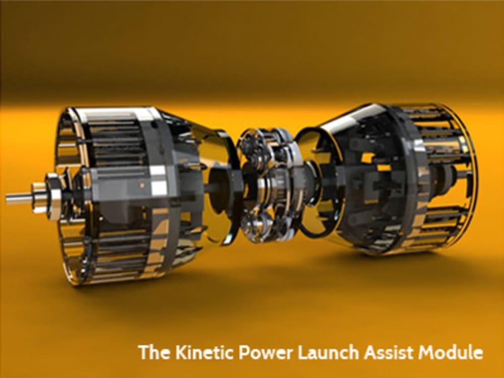
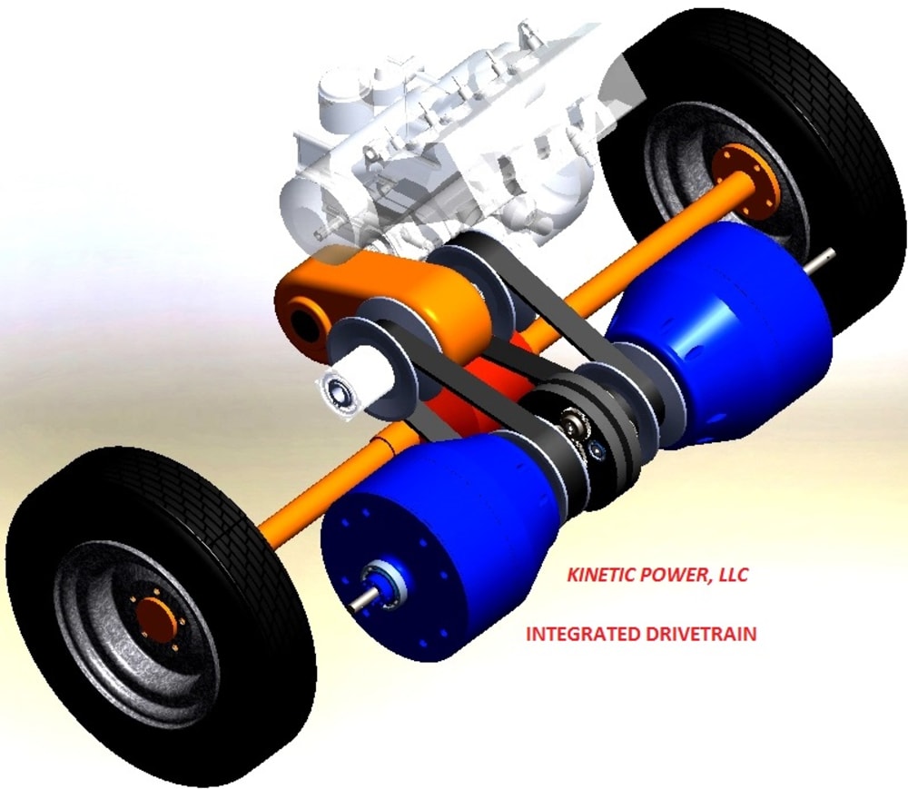
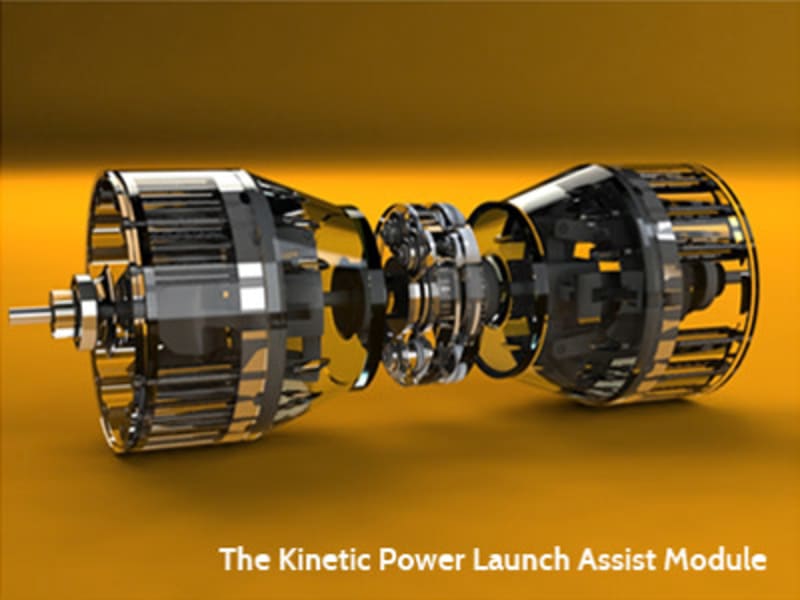
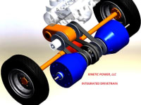
A novel flywheel-based system is being developed by Kinetic-Power, LLC, a firm set up by the two co-inventors of this system. The GraMar system requires two variable-inertia flywheels (VIF) coupled to a conventional or epicyclic differential in a manner such that the two inputs (or outputs, depending on which mode is being operated – acceleration or deceleration) are subtractive – that is, they are counter-rotating. The angular velocity of Flywheel A (VIF-A) is subtracted from the angular velocity of Flywheel B (VIF-B) at the output/input of the KERS differential.
When the two flywheel inputs/outputs are of equal angular velocity at the connection to the KERS differential, the output/input of the KERS differential will be zero. When the inertia of each flywheel is changed in opposite directions (for example, VIF-A inertia is decreased while VIF-B inertia is increased), in order to satisfy the law of conservation of momentum, their angular velocities will attempt to change – VIF-A angular velocity increases while VIF-B angular velocity decreases. These velocity changes are algebraically added and result in a torque being produced at the differential output.
The change in moments of inertia for the flywheels results in an accelerating torque on the differential output. An opposite change where an output angular velocity exists will result in a reverse torque thus decreasing the output angular velocity.
A control algorithm has been developed that insures a balanced torque on the differential and a balanced variable-inertia flyweight actuation system. This eliminates any possible recirculating power loss and a net-zero work input requirement for the actuation system. We are at the prototype stage looking for an industry partner.
-
Awards
-
 2016 Top 100 Entries
Like this entry?
-
About the Entrant
- Name:James Gramling
- Type of entry:individual
- Software used for this entry:Solidworks Premium Motion Analysis
- Patent status:patented