
This proposal is for an innovative mechanism to selectively reject material from an ore or other material stream on a conveyor, using a sensor to identify “parcels” of streaming material with a specific characteristic (grain size, color, fluorescence, etc.) on the conveyor and diverting those “off-spec” materials. The conveyor may carry the materials at 6 meters per second. The mechanism is robust, made primary of plate steel, which can withstand continuous daily operation over 6 months or more under the weight and energy of impact of falling ore or other material from the primary conveyor belt located above the hopper. The upper and lower conveyors and the main outer structure of the hopper remain fixed, while the inclined partition wall mechanism is capable of moving reciprocally, upon actuation by the sensor signal at an “upstream” location, in proximity to the upper conveyor belt delivering the material to the hopper. The diversion is performed by an extending horizontal motion within a limited distance inside the hopper which has two exit-ways.
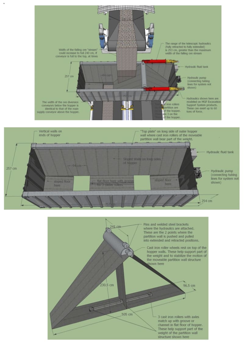
The weight of the inclined partition wall is supported by free-moving cast iron rollers- two on the upper part of the partition wall mechanism, and three on the lower part. These five rollers distribute the weight of the inclined partition wall mechanism, and the weight and force of the moving ore, over a larger area and ultimately down to the massive vertical I-beam columns that support the ore hopper structure. This is significant for durability and stable operation of the diversion mechanism. It is superior to trying to move the entire hopper structure, along with the exit-way from the hopper. Also, the conveyors themselves remain fixed in position.
The two rollers in the upper part of the inclined partition mechanism rest upon, and are free to roll along, the top of the longer outer walls of the hopper, while the three rollers attached by their axles to bearings fixed on the lower part of the partition mechanism rest upon and can roll along a groove or channel in the bottom of the fixed floor section of the hopper structure.
Each exit-way is located immediately above a receiving conveyor belt, so that when the hydraulic arms are fully extended, material pours into the main receiving conveyor located below the hopper, where most of the daily volume delivered by the upper conveyor is sent for delivery to the “meets-spec” material location at the end of that receiving conveyor. The telescoping hydraulic arms are depicted in the illustrations as “cylinders”, which are actually square in cross-section. When the hydraulic arms are fully retracted, the inclined partition wall component of the hopper is pulled toward the hydraulic arms, and the material that is “off-spec” for a time pours into the second exit-way, which delivers the rejected or diverted ore or other material to the second conveyor belt which delivers the “off-spec” ore or material to a separate location for collection. The hydraulics operate rapidly “meets-spec” material waste is minimal and all “off-spec” material is diverted.
Like this entry?
-
About the Entrant
- Name:Ted Ground
- Type of entry:individual
- Software used for this entry:Google Sketch Up Used to Illustrate Component Configuration and Dimensions
- Patent status:none