


This study aimed to design and develop a multi-purpose controller to measure and control moisture, temperature, and time. Specifically, it aimed to design and develop microcontroller circuit for the controller; make assembly language program for the microcontroller; evaluate the readings of moisture and temperature of each unit by measuring the moisture content and temperature of a crop processing machine. The study provides easy-to-use processing machines for farmers and small-scale crop processing entrepreneurs.
The system used assembly language program. PICKIT 2 Compiler was used to make the assembly language source program. The system flowchart was used as the basis in developing the assembly program. In the system flowchart, the controller started by choosing the unit to be used. The user also needed to choose the parameter/s. If moisture was to be used, the initial moisture automatically displays and then the user needs to input the final moisture. If temperature was to be used, the initial temperature automatically displays and then the user needs to input the final temperature. However, if processing time was to be used, the user needs to input the processing time and the countdown timer displays. Each unit used the moisture, temperature, and processing time either/or was present, which means that the machine needs to obtain the set moisture, and temperature, and finished the set processing time before the machine shutdown. The LED corresponding to unit lights-on indicates that the operation is ongoing and lights-off to indicate that the unit is idle. The three units were used in simultaneous operations.
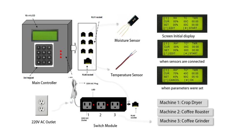
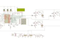
The entire circuit were constructed using Proteus software. The power supply circuit was constructed according to the circuits. It has two output 12 volts and 5 volts. The relay/switch module circuit was set as the interaction between the main controller and the machine. It then waits for the logic instruction of the microcontroller to shut down by recognizing logic “0” signal. RJ 45 and UTP (Unshielded Twisted Pair) cable connector was used to connect to the main controller. PIC16F877A microcontroller was the main part of the design project. The main function of the microcontroller circuit was to sense analog output being sent by the sensors then it also evaluates and confirms the instruction set by the keypad and displays its output to the LCD screen. The user will then select for the desired unit and select parameters and enter the desired values. When the values are met, the microcontroller will trigger the relay to shut down the machine.
The controller has undergone a series of tests for both hardware and software. The program was simulated in the software and burned to the microcontroller. In the picture of entire system it shows the display that will appear on the LCD screen when you turn on the main controller and when the sensors are connected, an asterisk (*) after RH and TC will appear, it also shows the moisture sensor that reads as 70% RH and temperature sensor that reads 40o Celsius.
Like this entry?
-
About the Entrant
- Name:Sheryl Dinglasan Fenol
- Type of entry:individual
- Software used for this entry:Proteus
- Patent status:none