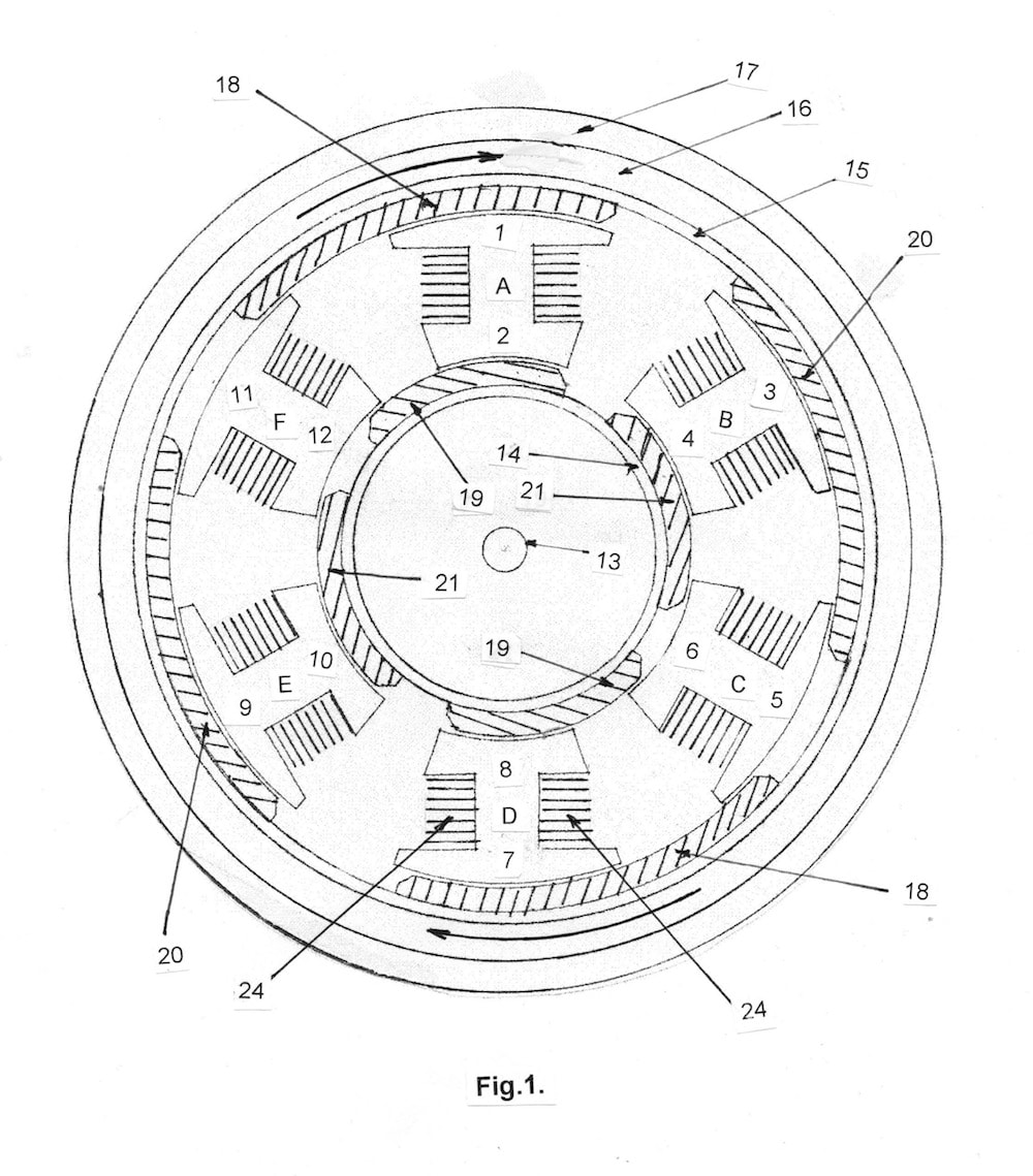
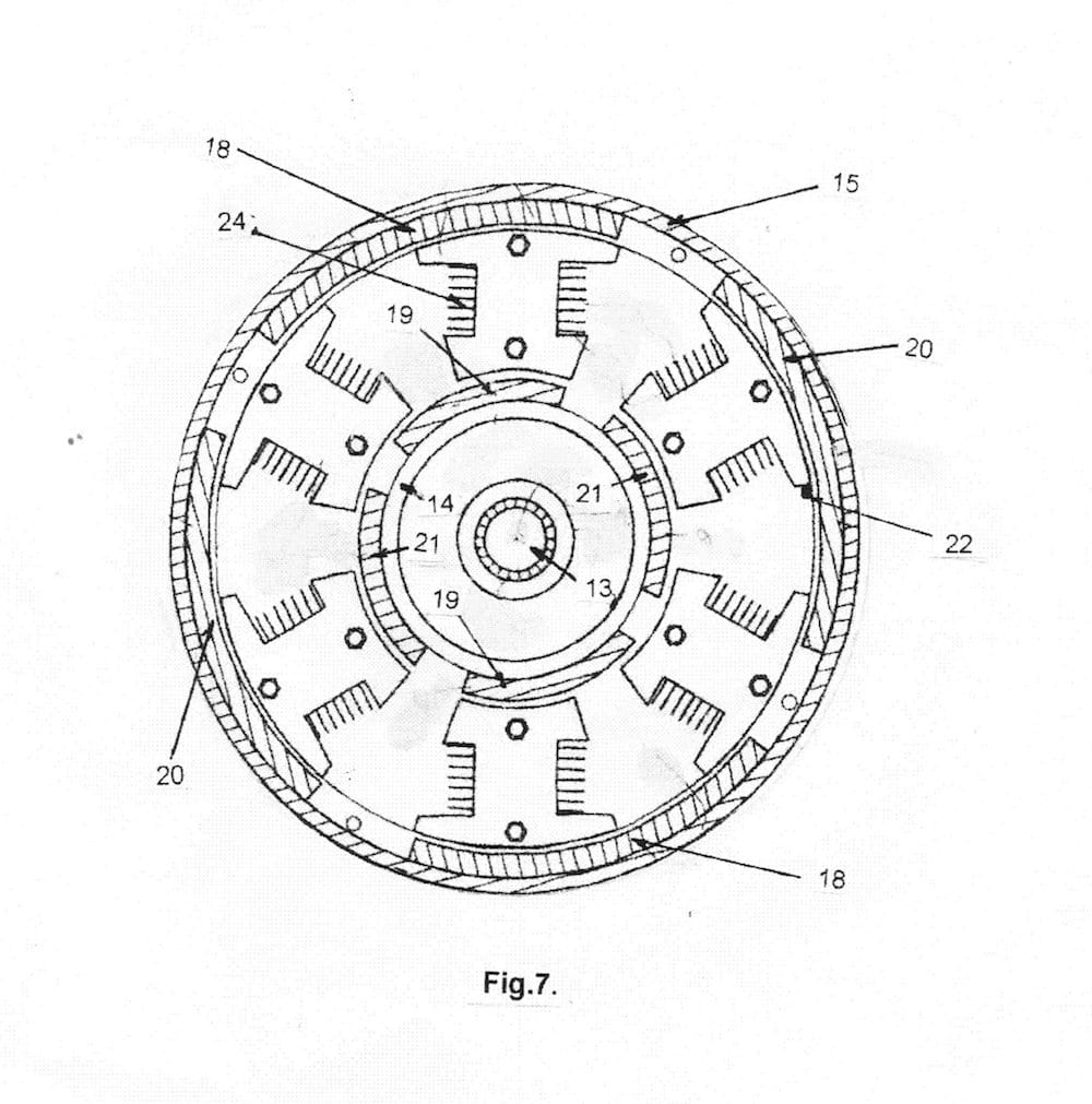


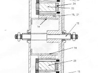
There have been many types of electric gear boxes and clutch systems, but they all use gears to mesh with one another, with friction pads or friction pads for the clutch, they tend to be complicated specialized mechanical equipment, this invention is a unique and innovative way of achieving both, giving a frictionless high performance, low cost, virtually maintenance free way of achieving both applications. By using the technology in US patent no.6.812,615 for an electric motor, which effectively uses both sides of the energised coil. There are 1.2 Billion Vehicles on the Worlds Roads with 253 Million cars and trucks on U.S. roads, plus there are many more application for the use of a gear box and clutches, planes, helicopters, wind turbines and other industrial eqipment are but a few. The system provides a means of forward and reverse propulsion and a means to slowing or braking of the rotor, in a gear box or clutch system in a in hub electric motor attached to a wheel. The system is housed with one part fitted with energised coils, which can also rotate, with the electric current suppied through slip rings, while the rotor is fitted with permanent magnets. To understand this invention if you isolate energised coil A and look at the end 1 Fig.1, and nominate it as a North magnetic pole, the permanent magnet 18 has a inside face of a South magnetic pole, the permanent magnet 18 will be attracted to the energised coil end 1, the permanent magnet 18 is now aligned over the center of the energised coil end 1, the direction of the electric current is change in energised coil A by the commutator or electronic controller, which now becomes a South magnetic pole, and as like magnetic poles repel, the permanent magnet 18 is repelled the inertia of the permanent magnet 18 would also have an effect on keeping it moving in the same direction. That is how an electric motor works, but to under stand how the electric brake works we again look at the energised coil A end 1, which is now a South magnetic pole, like magnetic poles repel, so the permanent magnet 18 would like to be repelled, but is forced in the direction of rotation by either inertia or friction, towards the center of the energised coil A end when it is over the center of end 1, the commutator or electronic controller changes the direction of the electric current, so now the magnetic pole at end 1 is now a North magnetic pole, and unlike magnetic poles attract, but the permanent magnet 18 is forced to move in the direction of rotation as the constant magnetic force is applied to stop the rotation of the permanent magnet 18, it will stop rotating and remain stationary, the force of braking is dependent on the amount of electric current and voltage applied, but it will be equal to the force and torque of the electric motor.
Like this entry?
-
About the Entrant
- Name:John Ettridge
- Type of entry:individual
- Patent status:pending