


In engines used before the late 1990s, the valve-lift of inlet and exhaust valve remain the same for all the speeds of the engine. This resulted into deviation in performance characteristics when the engine was not running at design point. The engine has to change its specifications according to its speed. There are many parameters which are to be changed constantly for better performance of the engine over a wide range of speed. The valve is one of the components that influences engine performance. Hence parameters related to the valve affect engine rendition. Valve-lift is a field where comparatively less research is done, and mechanism involving change in valve lift according to engine speed is central to our project. As developments are already done in this field, consisting of different mechanisms for change in valve-lift. An alternate design can also be made for improved performance of valve actuation. At low rpm of the engine, low valve lift is required and at high rpm high
valve lift is required. In conventional engines only one type of valve lift is possible. If we provide low lift for better performance at low rpm, performance at high rpm will be compromised, and if we provide high lift for better performance at high rpm, performance at low rpm will be compromised. That is why we required variable valve lift. This process is to be followed while the engine is running. So a mechanism rectifying this problem is to be designed because the actuation of this mechanism is crucial while the engine is running.
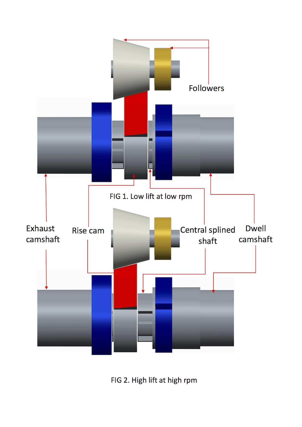
Mechanism consist of five parts:(shown in illustration)
1. Rise cam
2. Dwell cam on spline shaft
3. Exhaust spline shaft
4. Central spline shaft
5. Rise and dwell followers on rocker arm
Focus is on the shifting of central spline shaft axially when engine speed is changed, because shifting axially will ensure that different portion of rise cam will come in contact for different engine speeds. This speed can be sensed electronically and then with electronic and hydraulic components the shifting of shaft can be executed. It was required to have separate dwell cam and dwell follower, because if that had not been provided then there will be line contact between cam and follower when valve is to be in seated position. Here if this specific shape of dwell cam is not provided then at the end of rise portion of cam there will be jump of follower and that will lead to surface erosion and lots of noise.
Working:
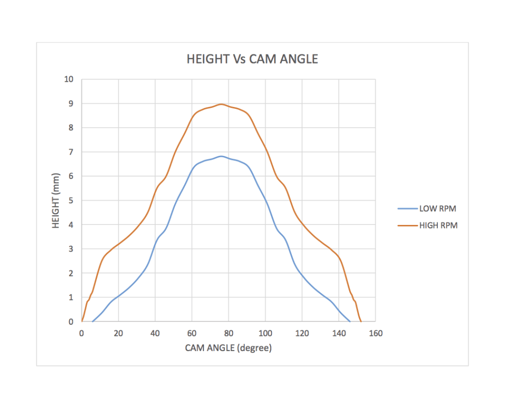
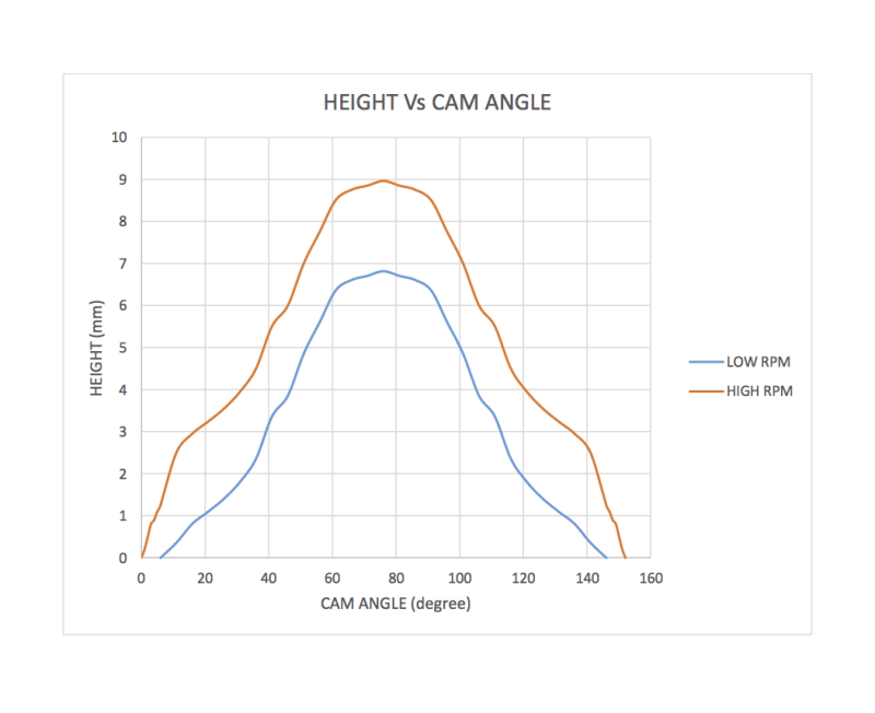
At low RPM: Smaller portion of rise cam in contact, gives lesser lift leads to lesser fuel consumption
At high RPM: High lift, more air-fuel mixture, smooth flow of it into engine and that leads to more power and lesser inlet losses
When valve is to be closed, the dwell cam will come in contact with dwell follower.
Like this entry?
-
About the Entrant
- Name:Meet Patel
- Type of entry:individual
- Software used for this entry:CREO and ANSYS
- Patent status:none