
LCMLM (Linear Controlled Magnetless Machine), features of this type of linear motor is that the high fault tolerance, low cost, competitive weight, due to the absence of permanent magnet. The aim of the project is to investigate and develop the use of Linear Controlled Magnetless Machine for railway braking operations/ though the applications can be used for driving (reversal of braking). Conventionally, train systems work based on the principles of adhesion of the wheels and track and friction, to slow down the train for braking. But the issues with these types of systems are the wear and tear of the mechanical system components due to the application of friction. Apart from that, a separate system needed to be installed only for braking, which only increase the weight of the system.
Which is why, if there is an alternative without PM, which produced high thrust force it would make a significant impact. The proposed is an improvement when being compared existing system of operation during motoring and braking. Linear Controlled Magnetless Machine uses pulses of current which overcomes the slip difference of conventional operational mode (happens both in accelerating and decelerating), to produce high mechanical force without the use of PM. A small DC coil is introduced that give the required energy through a controller thereby precise stopping is achieved and reducing the energy loss from the main braking system.
Thus with the idea to replace the permanent magnets, with electromagnetic coils, we can solve the issues arising due to PMs. Also, since the force produces is controlled solely by the current supplied to the system, it is easier and precise control of the force required during braking is highly feasible. This design is an adaption of the conventional maglev based train systems, using permanent magnets.
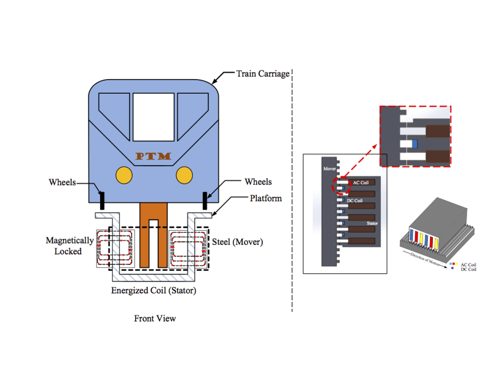
There are two main parts of the design:
1) Mover – Steel
2) Stator – Energized (armature) coil, DC coil.
The mover material was set as the steel, and the coils are designed to be placed in the stator, as it would be easier to supply energy to a stationary part when compared to the moving train.
The armature coil is supplied with current and with the help of the DC coil, produces a force on the mover, through the air gap. It is a frictionless system, because the mover and the stator is separated by an air gap, therefore, there is no worry about frequent maintenance due to the wearing out of the system components.
Like this entry?
-
About the Entrant
- Name:Preshant Krishna
- Type of entry:teamTeam members:Aravind C V
- Software used for this entry:SolidWorks
- Patent status:none