


Background: Over tightening of screws is common and results in damage to the screw’s thread.
I have developed a method which determines the optimal point in time to stop tightening the screw. The advantage over existing methods is that my method doesn’t require torque and rotation sensors and is therefore cheaper and easier to integrate into existing power tools.
Background:
The method on which the suggested invention is based happens to be well known in the field of mechanical engineering and is commonly termed "Yield Controlled Tightening" or "Torque to Yield." The method is best described by Figure 2 which shows a typical tightening torque of a screw relative to its tightening rotation angle.
As can be seen in figure 2, when a screw starts to tighten, its tightening torque vs. angle gradient becomes positive and relatively constant (section A-B). The linear region A-B is commonly called the elastic expansion region. Further tightening of the screw beyond point B will stretch it such that even when the tightening force is removed, the screw will no longer return to its original length. For this reason, this region is termed the plastic expansion region. The objective is to prevent the screw from reaching its yield point (marked C), the point after which damage starts to occur and to stop tightening at an optimal point between B and C. Detecting the optimal point automatically can be done by continuously monitoring the tightening torque and angle and calculating the torque vs angle gradient but such torque and rotation sensors are expensive and fitting them requires redesign of existing power tools.
Novelty:
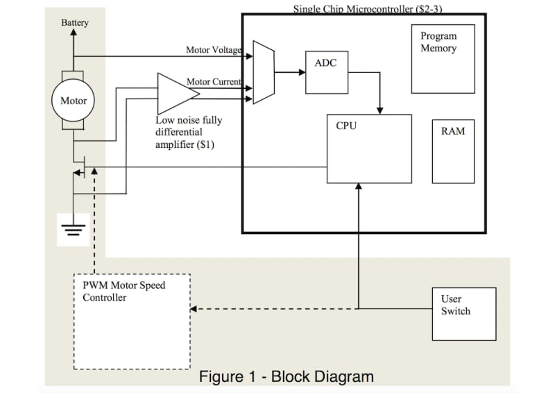
The novelty in my invention is that it requires none of these expensive sensors nor calibration or application-specific tailoring. The solution relies on measuring the voltage and current driving the motor and calculating the torque vs rotation gradient based on these measurements.
Figure 3 presents the true torque vs. rotation gradient along with an ideal (green) and proposed simplified (red) estimators. I’m unable to show the full mathematical derivation due to the 500 words limit and the simple text format restriction. The suggested estimator requires the voltage, the current and the motors inductance and resistance which can be estimated when the motor starts to spin. Note that the point in time to stop the motor (around 5 seconds in this simulation) depends on the relative drop from the maximum calculated gradient value. As can be seen, the plot shows remarkable similarity in relative drop between the true and the simple estimator.
Implementation:
The implementation is presented in Figure 1. This implementation replaces the commonly found PWM controller which is shown here for clarity.
Since DC motors exhibit a constant ratio between current and torque, the torque can be estimated easily by measuring the motor's current consumption.
Current can be estimated by measuring the voltage drop over the MOSFET switch which is by definition in its triode region and therefore exhibits linear resistance.
-
Awards
-
 2017 Top 100 Entries
Like this entry?
-
About the Entrant
- Name:Raanan Yechezkel
- Type of entry:individual
- Software used for this entry:Matlab
- Patent status:none