
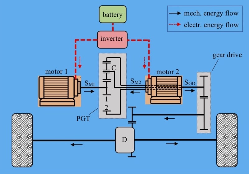
Regardless of a number of speed ratios ("speeds"), the transmission of existing electric vehicles always operates with a single degree of freedom(DoF): the required vehicle velocity results in strictly determined speed of the electric motor(s) propelling the vehicle. Of course, this is not an optimal motor speed for maximum motor efficiency. To be optimal, it should lie at the optimal operation line of the motor obtained by testing the motor and drawn in torque – speed diagram: for a known torque, there is a single optimal motor speed. Thus, it seems impossible to achieve the optimal motor speed for any vehicle velocity. But, it is possible! To get the optimal motor speed, its shaft should run independently of the wheels' speed, i.e. of the vehicle velocity. A planetary gear train perfectly meets the need. It has two DoFs, i.e. three rotating shafts: the first (e.g. SM1) is connected to (main) motor 1 that is going to be optimized, the second (e.g. hollow shaft SM2) to auxiliary motor 2, and the third (SGD), passing through the hollow shaft, is, over the gear drive and differential, connected to the wheels (see figure). Thus, the battery energy, over the inverter, feeds the motors, wherefrom, over the PGT, gear drive and differential propels the wheels.
According to the known Willis equation (relating the three PGT external shaft speeds), the speed of the higher sized, main motor becomes independent of the PGT output shaft SGD (i.e. of the vehicle velocity) as long as the third shaft (that of the auxiliary motor) runs at the speed that satisfies the Willis equation. By this topology, the speed of the main motor shaft can be optimized for maximum efficiency. For any vehicle speed, acceleration, and corresponding wheels' power demand, the speed of the PGT output shaft SGD is known for the control system as well as the main motor torque. From the known equation of the main motor optimal operation line, the power train control system calculates the optimal value of its speed and auxiliary motor speed (from the Willis equation) and forces the motors to run at those speeds. The required vehicle speed is achieved along with the maximum efficiency of the main motor. So, the huge energy saving is achieved at the expense of the low-sized additional motor. The auxiliary motor operation cannot be optimized, because its speed is determined by the main motor speed and vehicle velocity. However, by smart design of the transmission, firstly of the PGT, the operation points of the auxiliary motor can be moved to the area of high efficiency. The gear drive serves to harmonize the speed, torque, and power ranges of components with the PGT basic gear ratio and efficiency of the auxiliary motor.
It is to be stressed that the distribution of PGT shafts must not be as shown in the figure. In principle, sun gear 1, ring gear 2, and carrier C of PGT can be connected to either motor or SGD shaft.
Like this entry?
-
About the Entrant
- Name:Damir Jelaska
- Type of entry:individual
- Software used for this entry:Matlab/Simulink
- Patent status:pending