
In general, prototype models of aerospace vehicle, aircraft or high speed wing bodies (even in automobiles), objects are tested in a wind tunnel test facility to get theoretical data to design the object at optimum solutions. Wind tunnels are available in a large range of mach numbers at subsonic to hyper velocity flow range. Before testing a model with a wind tunnel test facility, it is necessary to calibrate the flow parameters such as pressure, mach number, velocity, density, temperature distribution throughout the test section of the wind tunnel in 3 dimensions. In practice for getting optimum solution it is assumed that the flow over a wing body or test specimen should be a laminar flow and its is not possible to achieve a matured laminar flow at the test section, as possible turbulence level can be reduced by using honeycomb before the test section for a subsonic wind tunnel, and by using an settling chamber for a supersonic wind tunnel it is found that the flow will not be a fully matured laminar one.
The flow angularity and flow characteristics in a supersonic wind tunnel play a conceptual role in test section should be measured at a mixture of flow velocity and it is usually calibrated by using either cone or wedge flow analyzing equipment. In the analysis it is noted that the sensitivities of the yaw meter is maximum when the wedge or cone angles are maximum, but it’s not possible to have a maximum angle cone or wedge because of the detached wave & tunnel blockage factors. The calibration of a supersonic tunnel includes determining the Mach number range, pressure range trough out the test section of various range of operating velocity.
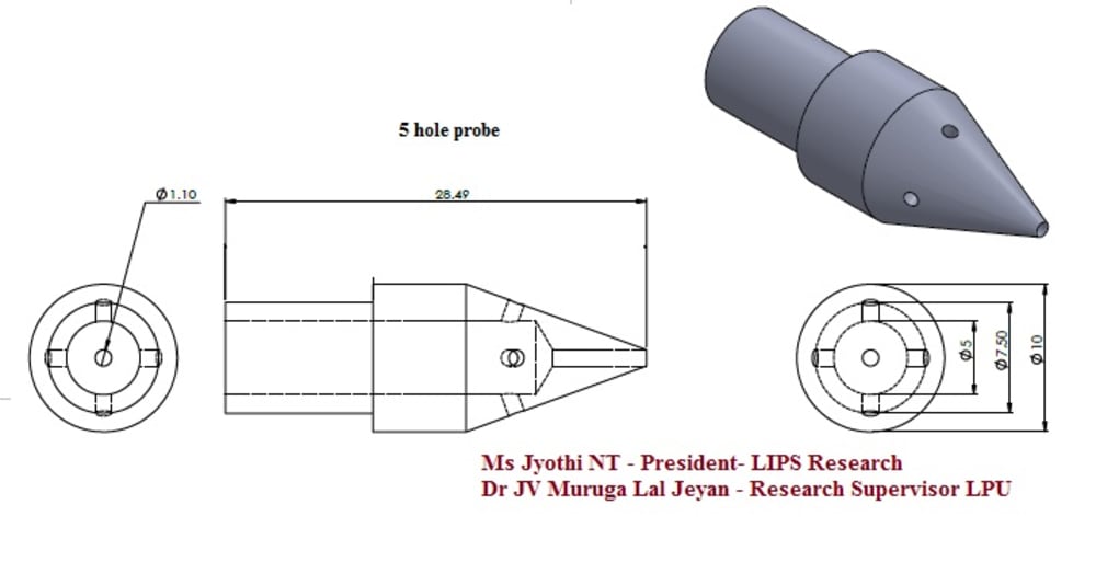
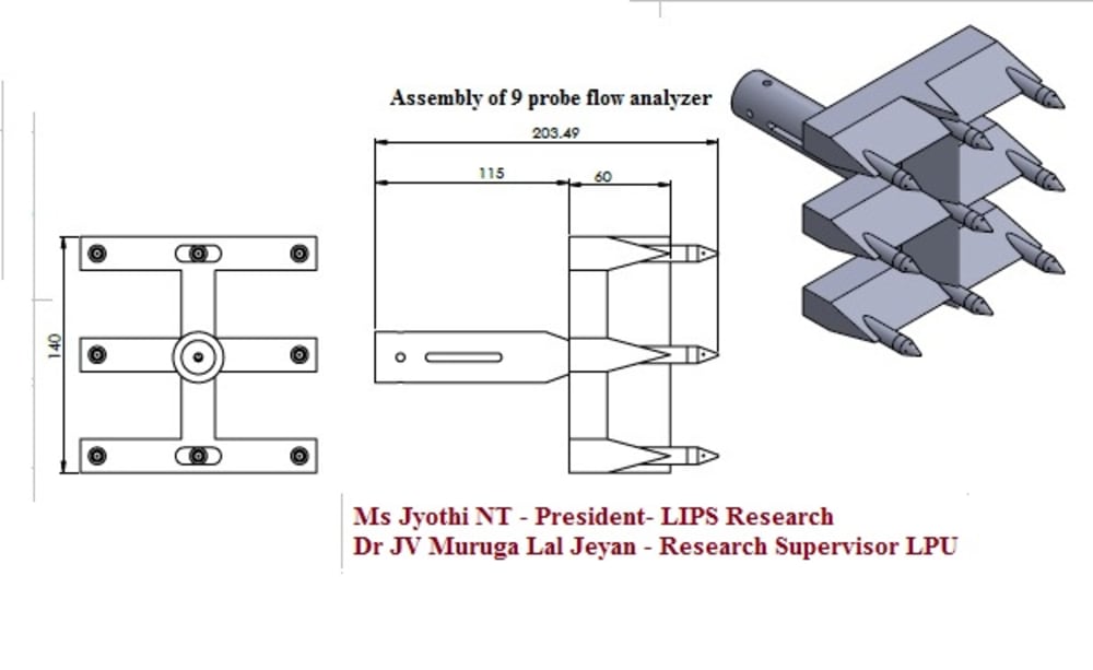
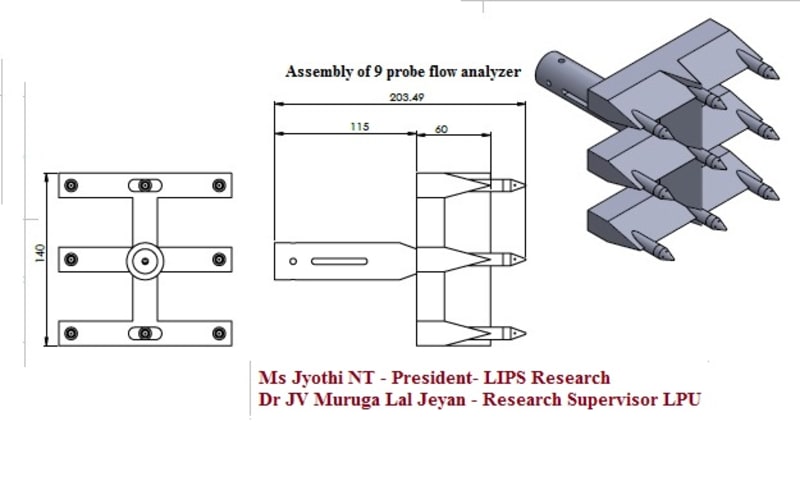
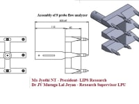
It is necessary to design a yaw meter to measure flow angularity inside the test section practically, Computational Analyses are carried out separately with 2 dimensional and 3 dimensional approaches. On the other hand, for problems such as the thermal analysis, wave angle, shock waves, blockage factors and considering the previous analysis and the existing data by accounting all the aerodynamic and mechanical loading a yaw meter can be designed for predicting the flow patterns at test section. The objective of the present thesis is to have a new design of yaw meter up to a mach number range of 0.3 to 2.5 and practically with 9 probes (45 tapings) The calculations will be validated by Computational approach an logically merging data with existing experimental results.
Like this entry?
-
About the Entrant
- Name:Dr Jv Muruga Lal Jeyan
- Type of entry:teamTeam members:Ms Jyothi NT- President - Lips Research
Dr JV Muruga Lal Jeyan - Research supervisor- LPU - Software used for this entry:Cos, Nastran, Catia, Ansys,
- Patent status:patented