
CHEMICAL BONDING ADHESIVE FOR BULK TRANSFER PIPE JOINT
Chemical Bonding system using adhesives to butt join two pipe ends providing an effective permanent long lasting leak-tight and strong joint. Correct designed Chemical joints are as strong as the pipe itself.
Purpose: Pipes for bulk transfer of gases and liquids have to be joined in the field and the standard welding process has many intrinsic problems that are sometimes difficult to overcome with the existing methods. Problems encountered include:
- Highly skilled operators are required
- Specialised equipment is required
- Joints between dissimilar materials are difficult and sometimes impossible
- Joining process is expensive
- Extensive tests need to be done to ensure reliable joints
- Joined pipes become electrical conductors prone to galvanic corrosion
- Dissimilar metals cause cathodic erosion
- Metal pipes have electrical currents induced which can be dangerous to workers
- Joints take long to be made and tested
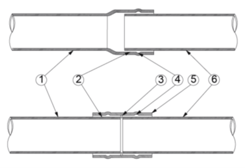
The CHEMICAL BONDING ADHESIVE PIPE JOINT SYSTEM, of which a typical example is shown in figure 1, consists of prepared surfaces, item 1 and Item 6, brought together and bonded to each other by applying an adhesive material Item 2 which can be brushed on, trowelled on, sprayed on, gravitated on or pumped onto the surfaces to be joined or the gap between them. The surfaces could be pipe ends in a spigot and bell design, a pipe and sleeve design or a pipe and clamp design. The spigot, sleeve, Item 5, or clamp could be an endless ring, a split ring, consisting of segments or could be one or more concentric or spiral wound strips and must provide an adequate and good surface for the adhesive to bond to.
The bell, sleeve or clamp can be provided with an opening through which the adhesive can be introduced. It could also be provided with a method of indexing to ensure that it fits correctly as per the design of the specific joint.
The adhesive, if non-conductive, will prevent the galvanic erosion of conductive pipes.
Making the joint, as shown in Figure 1, starts by laying pipe Item 1, slipping the sleeve Item 5, over the end then slipping pipe Item 6 into the sleeve. The index Item 3 locates the sleeve in the appropriate position. The adhesive is then pumped into the groove Item 4 which spreads the adhesive Item 2, evenly around the pipe end, Item 6, between the pipe and the sleeve. The adhesive is then pumped into the groove on the other side of the sleeve for the other pipe, Item 1. The adhesive is left to cure and the joint is complete.
Items 1 and 6 are the pipes to be joined
Item 2 is the layer of adhesive between the pipe and the sleeve
Item 3 is the index to retain the sleeve in position
Item 4 is the adhesive distribution groove
Item 5 is the sleeve or bell
Like this entry?
-
About the Entrant
- Name:Johan Van Niekerk
- Type of entry:individual
- Profession:
- Johan is inspired by:Experience, seeing challenges and solving them.
- Software used for this entry:CAD
- Patent status:none