


In this new concept CVT transmission of power is not by friction (as in conventional CVTs) in that case slip can occur, to prevent this slip high normal force is applied in existing CVTs; resulting in loss of transmission efficiency. In the new concept CVT transmission of power is by interlocking grooves and projections just as in synchromesh gears resulting in transmission efficiency comparable to synchromesh gears.
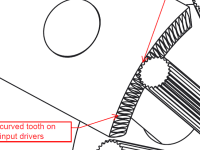
Salient feature of this concept is that the input and output pickups and rollers can be grooved to get transmission of power without any slip or frictional losses there by increasing transmission efficiency to that of the synchromesh gears. These grooves are parallel in the new concept, unlike conical (angular) in existing CVTs; so smooth (least friction) radial movement of pick-ups are possible without losing tangential rotating traction between pickups and rollers. So you can assume that the new CVT has both the advantages of CVT (Continuously variable) and gears (transmission efficiency).The driving force will be evenly spread between six number of pickups and their grooves so they will no tear off even though they are smaller than normal (existing) gear’s tooth; in case of normal gears driving force is applied on single tooth.
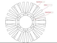
Rollers capable of rotating in their center axis are circularly and radially arranged on fixed shaft. And there are input drivers and output pickups that are radially movable inward and outward, those are constantly in touch with rollers and connected to input and output shafts respectively. Rollers on fixed shaft are positioned in the middle of input and output shafts.
Input drivers make the rollers rotate at a speed according to the radial position of the input driver. If the input drivers are located at outer most position the rollers rotate at highest speed and if the input driver is at inner most radial position the rollers rotate at least speed. And for the other in-between states of driver rollers rotate at those in-between speeds. The output pickups rotate at speed according to the speed of rollers and radial position of the output pickups. We can make the input-output ratio highest by positioning input driver at the outer most position and output pickup at the inner most position. We can make input-output ratio least by positioning input driver at the inner most position and output pickup at the outer most position. We can change the ratio to in-between states by positioning the pickups accordingly in the in-between positions. We can continuously vary ratio by smooth radial movement of both pickups those are in constant contact with rollers. See the drawings in following pages to understand the working of the concept; an animation of both pickups’ movement is also attached.
Video
Like this entry?
-
About the Entrant
- Name:Diji Jayakaran
- Type of entry:individual
- Patent status:pending