


The wind turbine with a contour tracer has turbine blades spinning around their own axis while orbiting around the central shaft vertically positioned on a horizontal rigid basement. A pair of hubs is mounted on bearings to the central shaft, positioned apart, at top and bottom of the said central shaft. A symmetrically positioned plurality of extended arms extended outwards around the central shaft, forming a rotor framework. Each turbine blade is integrated with an extension of shaft projected down words supported on pivots located on said extended arms of the said rotor framework.
A horizontal platform is having over the basement and it is drivable on bearings fitted to central shaft in order to adjust its orientation to face the turbine blades along desired direction.
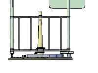
Down side of each turbine shaft is fitted with a crank arm, providing leverage to hold a roller to paddle along the track set on a horizontal platform disposed above the basement.
In operation, working cycle of each turbine blade is having a power stroke and a return stroke. During power stroke turbine blades are turned perpendicular to the direction of streaming wind whereas during the return stroke turbine blades are turned along the direction of wind. Concurrently, the turbine shafts are rotating about the central shaft, while the turbine blades turn around their own axis.
The turbine blade direction is controlled by the contour traced by the roller during power stroke. In operation, the said roller engages with the contour track and paddle between two guide walls of contour track, thereby turning the surface of the turbine blade perpendicular to wind direction and maintaining its direction during the first half circle of movement of the turbine blade. When the turbine blade moves to the extreme end, the contour track releases engagement of the roller thereby allows the turbine blade move freely. Then the turbine blade turns along streaming wind direction and produce minimum air resistance during its return stroke until it propel back on the other way round to the starting position. Thus another cycle continues by the roller engagement with the contour track.
The turning movement of the rotor geared to electricity power generator to produce usable electricity. Further, a break system and controls are accompanied to stop or reduce the rotational speed of the rotor and turbine blades.
The crank arm is designed in such a manner that the rear side of the rank arm is extended backwards so that a peg positioned on the bracket of the rotatable secondary platform, be impelled on the rear extension of the crank arm in order to turn the turbine on desired direction at the end of power stroke.
This wind turbine is low cost high efficient easy to assemble and build product. Its blades cover much larger area than a circular profile of the space of streaming wind. Power generator and control equipment are installed on ground level and reduces maintenance cost procedures. It can build to greater height.
Like this entry?
-
About the Entrant
- Name:Leelananda Jayasuriya
- Type of entry:individual
- Software used for this entry:AutoCAD, 3D studio max
- Patent status:none