


In most gear drives, due to inertial motion the driven output shaft becomes the driving one and the driving input shaft becomes the driven one. This condition is known as back-driving. In order to prevent this condition, different types of brake or clutch devices are used. However, there are also solutions in gear transmission that prevent inertial motion or back-driving using self-locking gears without any additional devices. The most common one is the self-locking worm gear with a low lead angle. However, worm gears has some limitations: very low gear mesh efficiency, relatively high gear ratio, the crossed axis shafts’ arrangement, low speed, or increased heat generation.
The proposed new self-locking gear actuators don't have such application limitations. They can utilize any gear ratio from 1:1 and higher. They can be external, internal, or incorporated into planetary gear stage or multistage gear systems. Their gear mesh efficiency is significantly higher than the worm gears and closer to conventional gears. The self-locking gears may find many applications in many industries, where position stability is very important in control systems.
Principle of Design
In a conventional gear system the input gear drives the output gear. In such cases the pitch point P is located in the active portion of the contact line B1-B2 (Figure 1a). This pitch point location provides low specific sliding velocities and friction, and, as a result, high driving efficiency. However, when such gears are driven by output load or inertia, they are rotating freely, because the friction torque is not sufficient to stop rotation. In order to make gears self-locking, the pitch point P should be located off the active portion of the contact line B1-B2 (Figure 1b). There are two options to satisfy this condition.
Option 1: The point P is placed between a center of the pinion O1 and the point B2, where the outer diameter of the gear intersects the contact line. This makes the self-locking possible, but the driving efficiency will be below 50%.
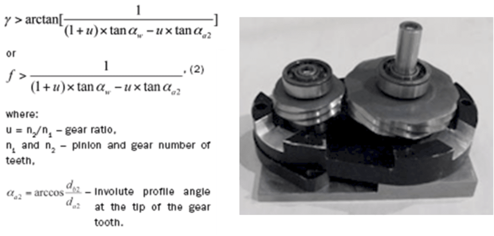
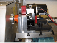
Option 2: The point P is placed between the point B1, where the outer diameter of the pinion intersects the line contact and the center of the gear O2. This type of gear can be self-locking with relatively high driving efficiency, above 50%. Another condition of self-locking is to have a sufficient friction angle gama to deflect the force F’ beyond the center of the pinion O1. It creates a resisting self-locking torque T’1 = F’ x L’1, where L’1 is a lever of the force F’1. This condition can be presented as L’1min > 0 (see Figure 2). The analytical and finite element analysis of this design has been validated and proved relatively high efficiency and reliable self-locking (Figure 3). The self-locking can have symmetric or asymmetric tooth profile depending on the load signature and application. It has a great potential in various industries such as in automotive, aerospace, medical, robotic, agricultural, textile, and food industries. Further detail information can be found in AGMA and Gear Solutions publication.
-
Awards
-
 2012 Top 100 Entries
Like this entry?
-
About the Entrant
- Name:Elias Taye
- Type of entry:teamTeam members:Dr Alex Kapelevich
- Software used for this entry:Ansys and Gear Design Software
- Patent status:patented